Monday, January 9, 2017

Controlling robot through Raspi UART

Once the UART port is configured to be used on the Raspi, now I can send commands to my microcontroller. For the purposes of showing how this works, I will make the robot move based on typical "WSDA" inputs from the keyboard. 

One key point to make about working with the Raspi's UART is that it operates at 3.3V. Arduino boards operate at 5V, so there needs to be some interface to convert the infromation from the Raspi up to 5V from 3.3V and convert the 5V from the Arduino down to 3.3V. Failure to do so can result in permanently damaging one or both devices. A perfect device for this is a cheap little Logic Level Converter. I have an earlier version of the one I linked in, but mine just has two less ports that the newer one. This device works pretty simply: it uses transistors as a switch to either turn 3.3V to 5V or 5V to 3.3V. See the schematic Sparkfun provides to get a better understanding of its operation. 

Robot setup
My robot chassis, from DFRobot, is expanded with an expansion plate to give me more room to mount sensors, batteries, etc. The overall robot setup can be seen to the right. The robot in its current form has 3 main subsystems: the Raspi and its GPIO header, the Arduino and stepper driver electronics, and the drive motors and wheels. I've used some standoffs to connect all the plates together in a format similar to other robot development platforms. 


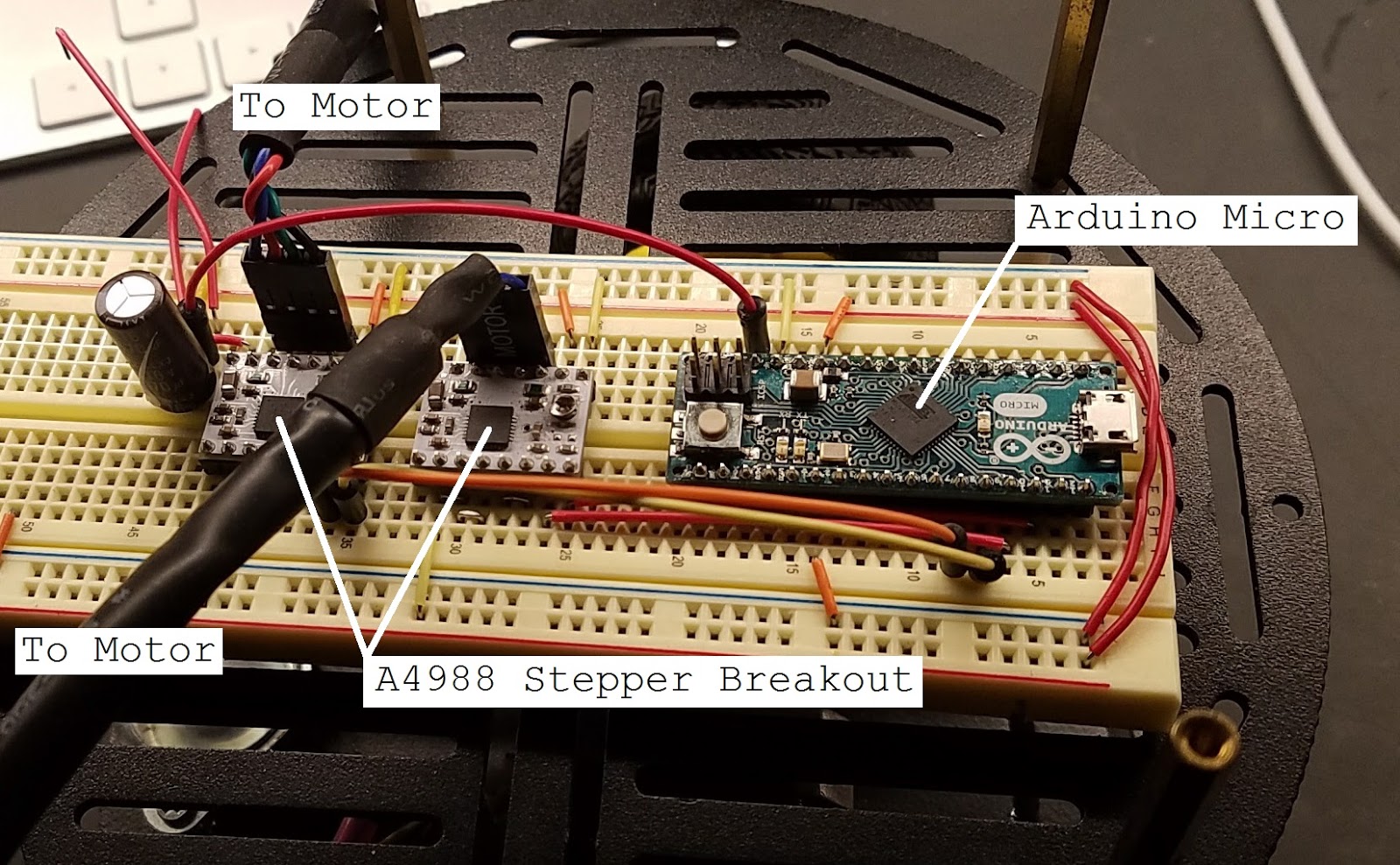
Motor control electronics
The Arduino Micro and the stepper drivers, A4988 stepper drivers from pololu, are in a breadboard for now. Eventually I will be soldering everything into a single board, but for now this gets things going to develop the software and make sure all my hardware works as expected. The stepper motors are connected directly to the breadboard through some standard .100" headers. There is also a 470uF electrolytic capacitor on the input from the 11.1V Li-ion battery that powers these electronics as well as the stepper motors. This sits on the second level of the robot with a 3000mAh USB battery pack for the Raspi. The first level holds the drive motors and wheels as well as the Li-ion battery. 


Raspi and subsequent electronics
The Raspi and the GPIO breakout sits on the top level. The breadboard holds the Raspi 3 GPIO Breakout and the logic level shifter for interfacing the Raspi with the Arduino. For now, only the transmit (TX) pin from the Raspi is connected to the receive (RX) of the Arduino since I have only so far needed one way communication. 

Below is a full schematic of how the electronics are connected for this example.


Schematic for UART control example
The UART pins from the Raspi, GPIO 14(TX) and 15(RX), are connected through the level shifter to the corresponding Arduino pins. The stepper drivers are connected to the Arduino in the same way as the previous post, but I included them for completeness. Note: All grounds should be tied together to ensure communications between the two devices operates as expected.  

Below is the C code that will run on the Raspi to send commands to the Arduino to control the motors. The Raspi will interpret "WSDA" commands and send the appropriate key characters to the Arduino and then the Arduino will interpret them as movement commands. Visit my Github repository to download the source code directly.


#include <stdio.h>
#include <stdlib.h>
#include <string.h>
#include <unistd.h>
#include <fcntl.h>
#include <termios.h>

int main(int argc, char* argv[]) {

 // Serial port structure for configuration
 struct termios serial;
 // Ports are defined like files in Unix
 char* port = "/dev/ttyS0";
 // Stores input key from keyboard
 char  key;

 // Print which port is going to be opened to console
 printf("Opening %s\n", port);

 // Open port
 int uartPort = open(port, O_RDWR | O_NOCTTY | O_NDELAY);

 // Check to make sure port was opened
 if(uartPort == -1) {
  perror("Failed to open port");
  return -1;
 }

 // Configure UART port
 // See http://man7.org/linux/man-pages/man3/termios.3.html
 //  for details on below configuration parameters
 serial.c_lflag = 0;  // Input modes
 serial.c_oflag = 0;  // Output modes
 serial.c_iflag = 0;  // Control modes
 serial.c_cflag = 0;  // Local modes
 serial.c_cc[VMIN] = 0; // Special characters
 serial.c_cc[VTIME] = 0; // Special characters
 serial.c_cflag = B115200 | CS8 | CREAD;

 // Apply configuration
 tcsetattr(uartPort, TCSANOW, &serial);

 // Run forever
 while(1) {
  // Read key entered
  scanf("%c",&key);
  // Process key value for direction 
  switch(key) {
   case 119: // w key
    printf("Up");
    // Write needs port, data pointer, and data length
    write(uartPort,&key,1);
    break;
   case 115: // s key
    printf("Down");
    write(uartPort,&key,1);
    break;
   case 100: // d key
    printf("Right");
    write(uartPort,&key,1);
    break;
   case 97: // a key
    printf("Left");
    write(uartPort,&key,1);
    break;
  }
 }
 close(uartPort);
}
Here is the code that runs on the Arduino. Note: The serial port used is Serial1, not Serial. Serial1 begins serial communications on the TX/RX pins rather then on the USB cable. When the proper character is received, the Arduino will configure the direction pins properly and then execute a quarter rotation of the motors. Since I am running the steppers at 16th step, there are 1.8 degrees per step for a total of 200 steps per revolution. This means that one complete revolution at 16th step is 200*16=3200 steps/revolution. So a quarter revolution is 800 steps.

// Define pinout
int leftStepPin = 7;
int leftDirPin = 8;
int rightStepPin = 9;
int rightDirPin = 10;
int curDir = 0;

char inChar;

void setup() {
  // Setup serial coms on TX/RX to get commands from raspi
  Serial1.begin(115200);
 
  // Configure right motor pins 
  pinMode(rightDirPin, OUTPUT);
  pinMode(rightStepPin, OUTPUT);
  digitalWrite(rightDirPin, HIGH);

  // Configure left motor pins
  pinMode(leftDirPin, OUTPUT);
  pinMode(leftStepPin, OUTPUT);
  digitalWrite(leftDirPin, HIGH);
}

void loop() {
  // Check if serial data available
  if(Serial1.available()) {
    inChar = (char)Serial1.read();
    // Process data
    switch(inChar) {
      case 'w':
        goForward();
        break;
      case 's':
        goBackward();
        break;
      case 'd':
        turnRight();
        break;
      case 'a':
        turnLeft();
        break;
    }
  }
}

void goForward() {
  // Set both motors for forward rotation
  digitalWrite(rightDirPin, LOW);
  digitalWrite(leftDirPin, LOW);
  // Rotate 1/4 revolution
  quarterRotation();
}

void goBackward() {
  // Set both motors for backward rotation
  digitalWrite(rightDirPin, HIGH);
  digitalWrite(leftDirPin, HIGH);
  // Rotate 1/4 revolution  quarterRotation();
}

void turnRight() {
  // Set left motor forward, right backward
  digitalWrite(rightDirPin, HIGH);
  digitalWrite(leftDirPin, LOW);
  // Rotate 1/4 revolution  quarterRotation();
}

void turnLeft() {
  // Set right motor forward, left backward
  digitalWrite(rightDirPin, LOW);
  digitalWrite(leftDirPin, HIGH);
  // Rotate 1/4 revolution  quarterRotation();
}

void quarterRotation() {
  for( int i = 0; i < 800; i++) {
    digitalWrite(rightStepPin,LOW);
    digitalWrite(leftStepPin,LOW);
    delay(1);
    digitalWrite(rightStepPin,HIGH);
    digitalWrite(leftStepPin,HIGH);
    delay(1);
  }
}
Once all the code is uploaded onto the Arduino and compiled to run on the Raspi, if you set up wifi on the Raspi, you can SSH, or Secure Shell, into the Raspi from a laptop and run the compiled code. There are a lot of great examples of how to connect to wifi and setup SSH on your Raspi out there, I'll leave it to you to google around and find out how to set that up.

With everything hooked up, here is a test run of code:

Monday, January 2, 2017

Setting up Raspi: UART

So one big addition to this new SLAM robot is the stereo cameras I plan on using to achieve visual odometry. I had a couple webcams I salvaged a bit ago and they were easy to mount onto a piece of aluminum I had laying around. They are both Logitech C270 webcams. They're not the best resolution, but since I plan on using an on board Raspberry Pi 3 to do the processing, the 720p resolution hopefully will allow for fast enough image processing on the Pi.
Stereo webcams on mounting plate.

Before I begin to implement any type of image processing or complex algorithms on the Pi, I must establish a link between the Pi and my microcontroller that will be interfacing with the stepper motors. Right now I am using a Arduino micro for the ease of implementation, however I eventually want to move over to using a PIC18F2550 microcontroller for size considerations. Starting with the Arduino and then porting the code over to the PIC might help some beginners reading this do the same. 

My Pi 3 is running Raspbian Jessie Lite, kernel version 4.4. Note that the following instructions are for the Pi 3, the UART port is changed on the Pi 3 from previous versions due to the addition Bluetooth. If you are familiar with using UART on previous Pi's, the UART lives at /dev/ttyAMA0. This port is now the connection to the Bluetooth controller. The UART on the Pi 3 is now at /dev/ttyS0. If you do not see this show up in your file listing, follow the bellow configuration and it should show up after. 

Configuring the UART:

1) Stop and disable serial service

    sudo systemctl stop serial-getty@ttyS0.serivce
    sudo systemctl disable serial-getty@ttyS0.service

2) Change command line boot options

    sudo nano /boot/cmdline.txt

You will see something similar to console=serial0,115200 in the file, remove this and any other mentions of serial0 and save the file.
Pi 3 header pinout.

3) Enable the UART pins

sudo nano /boot/config.txt

Append enable_uart=1 to the bottom of the file and save.

4) Reboot your Pi.

You should now be ready to use the UART on the Pi 3. To test that the configuration works, I connected the UART TX pin, GPIO14, to my oscilloscope to observe the output. 


#include <stdio.h>
#include <stdlib.h>
#include <string.h>
#include <unistd.h>
#include <fcntl.h>
#include <termios.h>

int main(int argc, char* argv[]) {

    struct termios serial;
    char* str  = "Hello, world!";
    char* port = "/dev/ttyS0";

    printf("Opening %s\n", port);

    int uartPort = open(port, O_RDWR | O_NOCTTY | O_NDELAY);

    if (uartPort == -1) {
        perror("Failed to open port\n");
        return -1;
    }

    // Set up UART port
    serial.c_iflag = 0;
    serial.c_oflag = 0;
    serial.c_lflag = 0;
    serial.c_cflag = 0;
    serial.c_cc[VMIN] = 0;
    serial.c_cc[VTIME] = 0;
    serial.c_cflag = B115200 | CS8 | CREAD;

    tcsetattr(uartPort, TCSANOW, &serial); // Apply configuration

    // Attempt to send and receive
    printf("Sending - %s\n", str);

    int r = write(uartPort, &str, strlen(str));
    if (r < 0) {
        perror("Failed to write to UART");
        return -1;
    }
    else {
        printf("Sent successful\n", r);
    }
    // Close port
    close(uartPort);
}
Compile the above code with sudo gcc main.c -o main, where main.c is the name of the file the code is in, and then run the compiled code with ./main

The output should look something like

Opening /dev/ttyS0     
Sending - Hello, world!
Sent successful        

The output capture on my scope verifies that the Pi 3 is transmitting our string from the UART. One important note about the waveform, the Pi 3's UART operates at 3.3V, however I have added in a transistor that switched 5V for future interfacing with the Arduino. This is why the waveform is on the 5V scale.

Scope waveform capture of "Hello, world!"