Around the Pittsburgh area there exists hundreds of thousands of mine tunnels beneath our feet. As communities expand and larger buildings are built up around these subterranean voids, the need for understanding and monitoring the health of these old mine tunnels and shafts becomes real. In conjunction with the Field Robotics Center at Carnegie Mellon University, I have been developing a robot capable of recovering 3D laser scans as well as visual color imagery from within these voids deployed through a borehole. The robot was developed originally by brothers Red and Chuck Whittaker and has gone through multiple iterations since the first one. They have come to be known as Ferret robots.
Front end of Ferrt, the 2D LIDAR in front, followed by the camera and the two large planar LED.
The business end of the robot is equipped with a oscillatory mechanism that houses a 2D SICK LIDAR and a CMOS blackfly camera with lighting. The basics con-ops of the device involves slow rotation of the mechanism to gather 3D laser data with visual imagery and then run a second scan, stopping at set positions to gather sequences of images for HDR image creation and 360 degree panoramic image stitching. The robot is controlled via ROS, with the computing handled with an onboard ODROID XU4. A Xsens MTi-20 VRU IMU onboard provides an estimate of attitude in order to properly combine the individual laser scans and imagery in the presence of any movement as the robot is gathering data.
Example scan of the FRC Highbay
I lead the full system development, from device driver software development and electrical design to the post-processing and auto-reporting software. The onboard software is a mixture of C++ and Python, involving ROS and OpenCV. Post-processing is currently prototyped in Matlab, but will possibly be moved to C++/OpenCV/PCL to increase speed. I am currently in the process of deploying the robot for the city of Pittsburgh to map subterranean voids near high traffic areas.
Once the UART port is configured to be used on the Raspi, now I can send commands to my microcontroller. For the purposes of showing how this works, I will make the robot move based on typical "WSDA" inputs from the keyboard.
One key point to make about working with the Raspi's UART is that it operates at 3.3V. Arduino boards operate at 5V, so there needs to be some interface to convert the infromation from the Raspi up to 5V from 3.3V and convert the 5V from the Arduino down to 3.3V. Failure to do so can result in permanently damaging one or both devices. A perfect device for this is a cheap little Logic Level Converter. I have an earlier version of the one I linked in, but mine just has two less ports that the newer one. This device works pretty simply: it uses transistors as a switch to either turn 3.3V to 5V or 5V to 3.3V. See the schematic Sparkfun provides to get a better understanding of its operation.
Robot setup
My robot chassis, from DFRobot, is expanded with an expansion plateto give me more room to mount sensors, batteries, etc. The overall robot setup can be seen to the right. The robot in its current form has 3 main subsystems: the Raspi and its GPIO header, the Arduino and stepper driver electronics, and the drive motors and wheels. I've used some standoffs to connect all the plates together in a format similar to other robot development platforms.
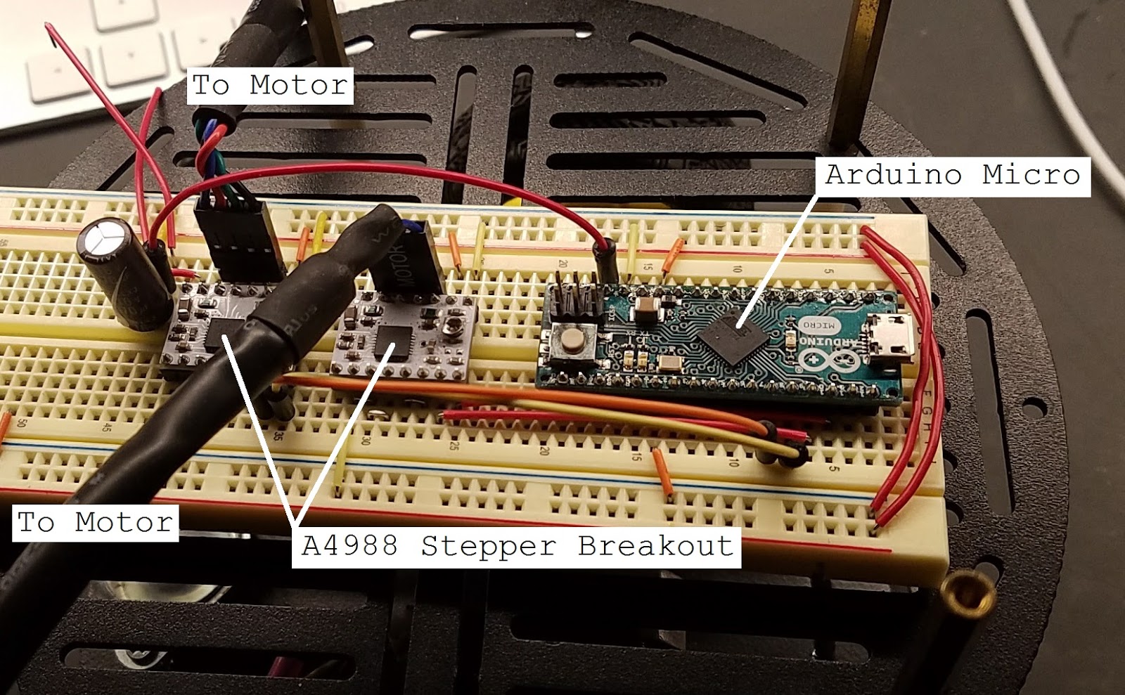
Motor control electronics
The Arduino Micro and the stepper drivers, A4988 stepper drivers from pololu, are in a breadboard for now. Eventually I will be soldering everything into a single board, but for now this gets things going to develop the software and make sure all my hardware works as expected. The stepper motors are connected directly to the breadboard through some standard .100" headers. There is also a 470uF electrolytic capacitor on the input from the 11.1V Li-ion battery that powers these electronics as well as the stepper motors. This sits on the second level of the robot with a 3000mAh USB battery pack for the Raspi. The first level holds the drive motors and wheels as well as the Li-ion battery.
Raspi and subsequent electronics
The Raspi and the GPIO breakout sits on the top level. The breadboard holds the Raspi 3 GPIO Breakout and the logic level shifter for interfacing the Raspi with the Arduino. For now, only the transmit (TX) pin from the Raspi is connected to the receive (RX) of the Arduino since I have only so far needed one way communication. Below is a full schematic of how the electronics are connected for this example.
Schematic for UART control example
The UART pins from the Raspi, GPIO 14(TX) and 15(RX), are connected through the level shifter to the corresponding Arduino pins. The stepper drivers are connected to the Arduino in the same way as the previous post, but I included them for completeness. Note: All grounds should be tied together to ensure communications between the two devices operates as expected. Below is the C code that will run on the Raspi to send commands to the Arduino to control the motors. The Raspi will interpret "WSDA" commands and send the appropriate key characters to the Arduino and then the Arduino will interpret them as movement commands. Visit my Github repository to download the source code directly.
#include <stdio.h>#include <stdlib.h>#include <string.h>#include <unistd.h>#include <fcntl.h>#include <termios.h>intmain(int argc,char* argv[]){// Serial port structure for configurationstruct termios serial;// Ports are defined like files in Unixchar* port ="/dev/ttyS0";// Stores input key from keyboardchar key;// Print which port is going to be opened to consoleprintf("Opening %s\n", port);// Open portint uartPort = open(port, O_RDWR | O_NOCTTY | O_NDELAY);// Check to make sure port was openedif(uartPort ==-1){perror("Failed to open port");return-1;}// Configure UART port// See http://man7.org/linux/man-pages/man3/termios.3.html// for details on below configuration parameters
serial.c_lflag =0;// Input modes
serial.c_oflag =0;// Output modes
serial.c_iflag =0;// Control modes
serial.c_cflag =0;// Local modes
serial.c_cc[VMIN]=0;// Special characters
serial.c_cc[VTIME]=0;// Special characters
serial.c_cflag = B115200 | CS8 | CREAD;// Apply configuration
tcsetattr(uartPort, TCSANOW,&serial);// Run foreverwhile(1){// Read key enteredscanf("%c",&key);// Process key value for direction switch(key){case 119:// w keyprintf("Up");// Write needs port, data pointer, and data length
write(uartPort,&key,1);break;case 115:// s keyprintf("Down");
write(uartPort,&key,1);break;case 100:// d keyprintf("Right");
write(uartPort,&key,1);break;case 97:// a keyprintf("Left");
write(uartPort,&key,1);break;}}
close(uartPort);}
Here is the code that runs on the Arduino. Note: The serial port used is Serial1, not Serial. Serial1 begins serial communications on the TX/RX pins rather then on the USB cable. When the proper character is received, the Arduino will configure the direction pins properly and then execute a quarter rotation of the motors. Since I am running the steppers at 16th step, there are 1.8 degrees per step for a total of 200 steps per revolution. This means that one complete revolution at 16th step is 200*16=3200 steps/revolution. So a quarter revolution is 800 steps.
// Define pinout
int leftStepPin =7;int leftDirPin =8;int rightStepPin =9;int rightDirPin =10;int curDir =0;char inChar;void setup(){// Setup serial coms on TX/RX to get commands from raspi
Serial1.begin(115200);// Configure right motor pins
pinMode(rightDirPin, OUTPUT);
pinMode(rightStepPin, OUTPUT);
digitalWrite(rightDirPin, HIGH);// Configure left motor pins
pinMode(leftDirPin, OUTPUT);
pinMode(leftStepPin, OUTPUT);
digitalWrite(leftDirPin, HIGH);}void loop(){// Check if serial data availableif(Serial1.available()){
inChar =(char)Serial1.read();// Process dataswitch(inChar){case 'w':
goForward();break;case 's':
goBackward();break;case 'd':
turnRight();break;case 'a':
turnLeft();break;}}}void goForward(){// Set both motors for forward rotation
digitalWrite(rightDirPin, LOW);
digitalWrite(leftDirPin, LOW);// Rotate 1/4 revolution
quarterRotation();}void goBackward(){// Set both motors for backward rotation
digitalWrite(rightDirPin, HIGH);
digitalWrite(leftDirPin, HIGH);// Rotate 1/4 revolution quarterRotation();}void turnRight(){// Set left motor forward, right backward
digitalWrite(rightDirPin, HIGH);
digitalWrite(leftDirPin, LOW);// Rotate 1/4 revolution quarterRotation();}void turnLeft(){// Set right motor forward, left backward
digitalWrite(rightDirPin, LOW);
digitalWrite(leftDirPin, HIGH);// Rotate 1/4 revolution quarterRotation();}void quarterRotation(){for(int i =0; i <800; i++){
digitalWrite(rightStepPin,LOW);
digitalWrite(leftStepPin,LOW);
delay(1);
digitalWrite(rightStepPin,HIGH);
digitalWrite(leftStepPin,HIGH);
delay(1);}}
Once all the code is uploaded onto the Arduino and compiled to run on the Raspi, if you set up wifi on the Raspi, you can SSH, or Secure Shell, into the Raspi from a laptop and run the compiled code. There are a lot of great examples of how to connect to wifi and setup SSH on your Raspi out there, I'll leave it to you to google around and find out how to set that up. With everything hooked up, here is a test run of code:
So one big addition to this new SLAM robot is the stereo cameras I plan on using to achieve visual odometry. I had a couple webcams I salvaged a bit ago and they were easy to mount onto a piece of aluminum I had laying around. They are both Logitech C270 webcams. They're not the best resolution, but since I plan on using an on board Raspberry Pi 3 to do the processing, the 720p resolution hopefully will allow for fast enough image processing on the Pi.
Stereo webcams on mounting plate.
Before I begin to implement any type of image processing or complex algorithms on the Pi, I must establish a link between the Pi and my microcontroller that will be interfacing with the stepper motors. Right now I am using a Arduino micro for the ease of implementation, however I eventually want to move over to using a PIC18F2550microcontroller for size considerations. Starting with the Arduino and then porting the code over to the PIC might help some beginners reading this do the same. My Pi 3 is running Raspbian Jessie Lite, kernel version 4.4. Note that the following instructions are for the Pi 3, the UART port is changed on the Pi 3 from previous versions due to the addition Bluetooth. If you are familiar with using UART on previous Pi's, the UART lives at /dev/ttyAMA0. This port is now the connection to the Bluetooth controller. The UART on the Pi 3 is now at /dev/ttyS0. If you do not see this show up in your file listing, follow the bellow configuration and it should show up after. Configuring the UART: 1) Stop and disable serial service sudo systemctl stop serial-getty@ttyS0.serivce sudo systemctl disable serial-getty@ttyS0.service 2) Change command line boot options sudo nano /boot/cmdline.txt You will see something similar to console=serial0,115200 in the file, remove this and any other mentions of serial0 and save the file.
3) Enable the UART pins sudo nano /boot/config.txt
Append enable_uart=1 to the bottom of the file and save.
4) Reboot your Pi. You should now be ready to use the UART on the Pi 3. To test that the configuration works, I connected the UART TX pin, GPIO14, to my oscilloscope to observe the output.
#include <stdio.h>
#include <stdlib.h>
#include <string.h>
#include <unistd.h>
#include <fcntl.h>
#include <termios.h>

int main(int argc, char* argv[]) {

    struct termios serial;
    char* str  = "Hello, world!";
    char* port = "/dev/ttyS0";

    printf("Opening %s\n", port);

    int uartPort = open(port, O_RDWR | O_NOCTTY | O_NDELAY);

    if (uartPort == -1) {
        perror("Failed to open port\n");
        return -1;
    }

    // Set up UART port
    serial.c_iflag = 0;
    serial.c_oflag = 0;
    serial.c_lflag = 0;
    serial.c_cflag = 0;
    serial.c_cc[VMIN] = 0;
    serial.c_cc[VTIME] = 0;
    serial.c_cflag = B115200 | CS8 | CREAD;

    tcsetattr(uartPort, TCSANOW, &serial); // Apply configuration

    // Attempt to send and receive
    printf("Sending - %s\n", str);

    int r = write(uartPort, &str, strlen(str));
    if (r < 0) {
        perror("Failed to write to UART");
        return -1;
    }
    else {
        printf("Sent successful\n", r);
    }
    // Close port
    close(uartPort);
}
Compile the above code with sudo gcc main.c -o main, where main.c is the name of the file the code is in, and then run the compiled code with ./main The output should look something like Opening /dev/ttyS0 Sending - Hello, world! Sent successful The output capture on my scope verifies that the Pi 3 is transmitting our string from the UART. One important note about the waveform, the Pi 3's UART operates at 3.3V, however I have added in a transistor that switched 5V for future interfacing with the Arduino. This is why the waveform is on the 5V scale.
I've begun the steps necessary to restart my original SLAM project I posted some time ago. I always wanted to not only complete the project but keep up this blog to document my progress and hopefully help others in their robot endeavors.
Added stepper motors.
I will be using the same platform as the original post, however I have changed over to using stepper drive motors instead of the cheap DC gear motors I was using. The motors were retrofitted onto the robot chassis with a few new holes drilled and taking a hot iron to the wheels to make room for the stepper motor shafts. I used AutoCAD to make a 1:1 layout of the motor mount and the location of the new mounting holes for steppers. I've run some tests on controlling the stepper motors with an Arduino Micro and two A4988 Stepper controller breakout boards from Pololu. They are in 16th step mode to reduce the speed of the robot, this is accomplished by tying the 3 MS# pins to +5V, see the datasheet for details.
Test schematic.
Using the above setup and the following code, I was able to make the robot move forward and back for a full rotation continuously.
// Define pinout
int leftStepPin = 7;
int leftDirPin = 8;
int rightStepPin = 9;
int rightDirPin = 10;
int curDir = 0;

void setup() {
  // Start serial coms
  Serial.begin(9600);

  // Configure right motor pins
  pinMode(rightDirPin, OUTPUT);
  pinMode(rightStepPin, OUTPUT);
  digitalWrite(rightDirPin, HIGH);

  // Configure left motor pins
  pinMode(leftDirPin, OUTPUT);
  pinMode(leftStepPin, OUTPUT);
  digitalWrite(leftDirPin, HIGH);
}

// Loop function
void loop() {

  // Complete single rotation of motor
  for( int i = 0; i < 3200; i++) {
    digitalWrite(rightStepPin,LOW);
    digitalWrite(leftStepPin,LOW);
    delay(1);
    digitalWrite(rightStepPin,HIGH);
    digitalWrite(leftStepPin,HIGH);
    delay(1);
  }

  // Swap direction for each motor
  if( curDir == 1 ) {
    digitalWrite(rightDirPin, LOW);
    digitalWrite(leftDirPin, LOW);
    curDir = 0;
  }
  else {
    digitalWrite(rightDirPin, HIGH);
    digitalWrite(leftDirPin, HIGH);
    curDir = 1;
  }
}
Purpose: Explore the subject of simultaneous localization and mapping (SLAM) robots. I have separated this venture into sever phases that are designed to build upon the previous. Here is a short description of my plan: Phase 1: Build simple Arduino robot that gets environment data from various ultrasonic distance sensors and begin trying to map the robot's surroundings Phase 2: Replace Arduino with raspberry pi, ultrasonic sensors with a Xbox Kinect sensor and begin implementing some of the more robust algorithms to make the mapping more accurate Phase 3: Replace raspberry pi with on-board computer, Kinect sensor with LIDARs, and fully implement SLAM. This is a tentative plan and will involve quite a few steps in between each phase, but should be a good template for later revisions. What is SLAM? From the name, you can guess that I are trying to map an environment and at the same time pinpoint the robot's location within said map. The difficulty with SLAM is that it produces sort of a catch-22. In order to know where you are within an environment, you must first have a map of your environment to compare what your sensor data shows. However, you do not have a map and must build one, but in order to build one you must first know where you are within the map you are building[1]. 4 Steps of SLAM [1]:
Acquire sensor data
Discern from the data any landmarks (walls, chair legs, etc.)
Compare found landmarks with know ones via data association
Update location and map
Phase 1 Hardware The system consists of two parts: (1) Arduino controlled robot (2) A laptop running Matlab
The robot is controlled by an Arduino Mega 2560. I chose this over an Uno or just using a PIC micro because at this stage I need a controller that is easy to setup, easy to program, and has the necessary amount of pins for the robot's sensor payload and other hardware. I have an Arduino Motor Shield on the Mega to interface with the DC drive motors. The chassis of the robot is the DFRobot 2WD Mobile Platform with a Prototyping Plate, also from DFRobot, added to make room for more hardware. So, the robot is a 2WD, 3 tier robot, with the prototyping plate in the middle. The prototyping plate is home to the Mega+Motor Shield, the Xbee, a breadboard to disperse power to sensors, and a 9V battery to power the Mega. Figures 1, 2 and 3 show the robot from the front, left, and right sides, respectively (note: ultrasonic array not depicted). The top of the robot is home to the ultrasonic sensor assembly, which includes the sensor array from Figures 4 and 5, as well as the servo motor that swings it around during data acquisition.
Figure 1: Front side of robot
Figure 2: Left side of robot
Figure 3: Right side of robot
4 Steps of SLAM: Phase 1 Implementation:
Acquire sensor data
The sensors I am using is a Parallax PING))) ultrasonic distance sensors. I have 3 sensors mounted on a fixture that is attached to a servo motor that sweeps the array around 180 degrees. Figure 4 and 5 show the configuration.
Figure 4: Top of sensor array. Sensors are angles 45 degrees apart.
Figure 5: Front of sensor array.
The servo the sensors are attached to can rotate 180 degrees, so with one scan, I am able to get a 270 degree view of the robot's surroundings. Before beginning this post, I did some validation testing of whether or not these sensors were robust/reliable enough to get good looking data. During this testing I only used the sensor position at 90 degrees to gather data, so only 180 degrees will be shown. Figure 6 shows an overlay of the data I got onto the surface I scanned (my workbench).
Figure 6: Distance readings overlay on workbench.
This is the raw output of the ultrasonic sensor. I was pretty happy with the results of this test considering its only a $30 sensor giving me only 2D data. I am hoping with the addition of the other 2 sensors I will get better definition of objects. Before I move on with more data acquisition, I did some simulations of how my dead-reckoning algorithms would hold up on this current platform. Unfortunately, I went the low-cost route for my motor encoders and they only have 10 ticks/rev (I know, its horrid). So, I developed a small Matlab simulation that imports a true travel path and exports a measured path that includes measurement error and a basic Kalman filter adjusted path to try and better predict the robot's position. Figure 7 shows a single run of the simulation and Figure 8 shows the error that accumulated during simulation.
Figure 7: Single run of dead-reckoning simulation. Estimate path is Kalman filtered.
Figure 8: Resultant error between the estimated position versus the true position.
From Figure 8, it is clear that since the encoders have such low resolution, that the largest impact is going to be on the robot's heading.